ATMOSSAT™
Updated: Sep 26
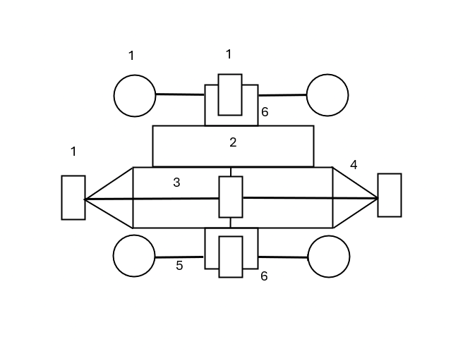
System Modules
The model is not to scale. Modules may be also multiplied or divided, for stability and scale. Odd numbers of rotary modules provide more stability than even numbers.
Bi-directional, axial rotational, Electric Turbofan & Motor/Dynamo x 3
Buoyancy Module
2.1 Semi-evacuated and partially, low pressure helium gas filled, hollow cylinder chamber.
2.2 Semi-vacuum and partially, low pressure helium gas filled, hollow cylinder.
(Lithium battery housed below.) or
The Xerqon HaloDrive may be a more appropriate substitute for the buoyancy module. It has the potential for greater mechanical stability. A redundant HaloDrive must be included.
The ATMOSSAT should be built to autorotate to the surface, on turbofans.
Buttressed, structural support frame strut
Turbofan, support frame struts to match number of turbofans
Dynamo on independently and freely pivotally rotating, vertical axes x 2 - above and below the cylinder chambers

The platform would mount communications or sensory devices from the base of the alternator at 6, at the lowest portion of Figure 1.
Technical Summary
The Atmosmpheric Satellite (ATMOSSAT) is the most convenient satellite platform to task and re-task, as well as for cost effective deployment.
ATMOSSAT will replace GPS satellites and surveying or surveillance satellites. Most of the satellite should be made of white, Nular (see article) and strengthened, skeletally, with aluminium carbide bracing, brackets and fulcrums etc. Wind will power the satellite completely, with battery support.
ATMOSSAT is equipped with electric turbofans for horizontal thrust, vectored by changes in fan speed-pairing ratios. Two oppositely placed fans will always compress air with the same relative force as each other. The other fans will vary from zero force to maximum force, based on how the ATMOSSAT is tasked. The generated air flow is bidirectional in capability. It can be forced to rotate in each fan direction.
The platform is air-braked by a wind generator of three turbofans top and bottom of the ATMOSSAT with dynamos to generate power from the dampened wind shear force. The battery will charged by the wind exclusively. It will not reflect light to overhead orbital satellites.
The dampening of the air and a central, vertically axially placed gyroscope will keeping the ATMOSSAT on a very small atmospheric footprint. It will outperform an orbital satellite for visual surveying.
The buoyancy is what keeps the device airborne. It is a hollow, cylindrical chamber filled with a low pressure volume of helium gas. It is a solid shell balloon - more robust than a ploymer film balloon. It is launched without any alternative power plant.
Small versions can be hand launched - both under buoyancy alone. A radio controlled actuator can lower an grapnel eye to the ground on a high gauge, shark fishing line where the device can be power winched to the ground, for the final stage of descent. That would be less than the remaining, essentially vertical 100m. Most of the descent will occur when the piston column is reduced to elicit an internal pressure comparable to the surroundings atmospheric pressure.
The helium chamber is at full expansion for sustainable buoyancy. The chamber is at its highest internal pressure and lowest volume for descent. No power should be required for the expanded position of the telescopic piston array. Power is required to retract the array.
Economies of scale will lower the price of the already low cost, mostly ploymer cosntructed device to near negligible comapred with orbaital platforms.
The frame can be internally bolstered with aluminium carbide for lightness and low torsion stuctural strength. ATMOSSAT is the current option for satellite development and acquisition for sensible, industrialised and other advanced economies.
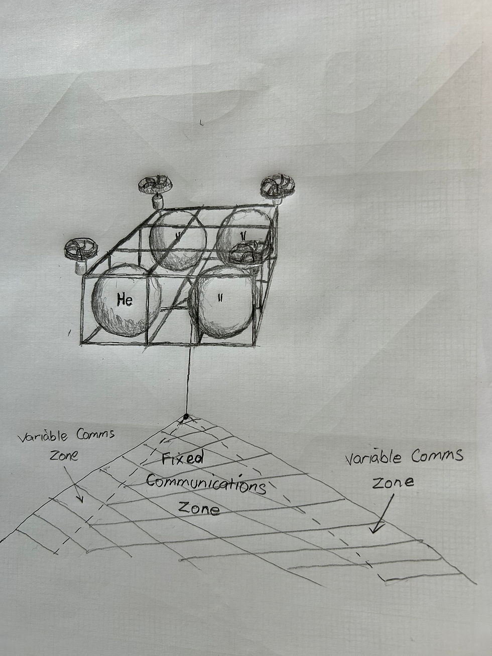
Early Pencil Sketch
© Xerqon Pty Ltd 2026


Comments